One Shot 555 Timer Schematic - Is There A Way To Prevent Re Trigger On One Shot 555. In all the designs the signal applied at trigger pin 2 are appropriately dimensioned to form a negative edged pulse. Using the 555 timer ic in special or unusual circuits nuts volts magazine from www.nutsvolts.com maybe you would like to learn more about one of these? The 555 and its complement, the 556 dual t imer, exhibit a typical initial timing accuracy of 1% with a 50ppm/c timing drift with temperature. This calculator is designed to compute for the output pulse width of a 555 timer monostable circuit. 555 timer was first introduced by signetics corporation in 1971 as se555/ne555.
555 timer was first introduced by signetics corporation in 1971 as se555/ne555. Boffins often also refer to it as a monostable multivibrator. The higher the values, the longer it stays high. Use the diagram below to connect the circuit: Before that let's take a brief idea of the 555 timer ic.
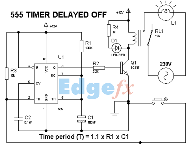
555 Timer Tutorial The Monostable Multivibrator from www.electronics-tutorials.ws The circuit produces accurate pulses whose time can easily be adjusted, based on the r1 x c1 time constant. Determine the value of capacitor, c, needed using r a r b 7.5 k. 555 ic automatically switches back to. How to make a simple led flashing circuit using 555 timer ic; The main role in this circuit is played by the 555 timer ic. The 555 ic timer circuit above shows a very straightforward design where the ic 555 forms the central controlling part of the circuit. The output pulse width (t) is calculated with the following formula. Following a schematic diagram i put together, i do a step by step build of a 555 time wired in monostable multivibrator (one shot) mode and explain how it wo.
Its name is derived from three 5k ohm resistors ,connected in series used in it.the timer ic can produce required waveform accurately.
An external triggering is required for transition from stable to unstable state. Please check schematic for 555 timer one shot of 100ms: In a previous video, she did an overview of the 3 different modes in which a 555 timer can be used. The output pulse width (t) is calculated with the following formula. You can also connect the output of any project to trigger the timer in the place of the push switch s1/ trigger switch. In the place of the push switch s1 / trigger switch you can also connect the output of any project to trigger the timer. After one timing cycle is completed this circuit doesn't repeat its timing cycle after we push switch s1 on or it remains pressed. The best known timer ics are the '555' family of devices, which are available in both single (555) and dual (556) bipolar packages and also in. 555 timer was first introduced by signetics corporation in 1971 as se555/ne555. Sketch the circuit of a 555 timer connected as an astable multivibrator for operation at 350 khz. The 555 and its complement, the 556 dual t imer, exhibit a typical initial timing accuracy of 1% with a 50ppm/c timing drift with temperature. This circuit uses very basic components like 555 timer and 4017 counter. Use the diagram below to connect the circuit:
The time it stays high is decided by the size of a resistor and a capacitor. Adjustable on off timer(using 555 astable mode) in this circuit a timer with cyclic on off operations is designed. In the place of the push switch s1 / trigger switch you can also connect the output of any project to trigger the timer. In a previous video, she did an overview of the 3 different modes in which a 555 timer can be used. One shot 555 timer schematic.
555 Timers 556 Timers 7555 Timers Basics Features And Application from www.elprocus.com If you connect a buzzer to the output, you can create an alarm circuit that is triggered for example by a window being opened. How to make a simple led flashing circuit using 555 timer ic; You can also connect the output of any project to trigger the timer in the place of the push switch s1/ trigger switch. After one timing cycle is completed this circuit doesn't repeat its timing cycle after we push switch s1 on or it remains pressed. Simple 555 timer circuits & projects. Check spelling or type a new query. When you start it, the timer turns on the output, waits for the time interval to elapse, and then turns the output off and stops. Determine the value of capacitor, c, needed using r a r b 7.5 k.
The inverted pulse output from a one shot monostable 555 timer circuit.
Monostable multivibrator (mmv) mode of 555 timer ic is also called single shot mode. Note the three 5k resistors on the left that create a voltage divider; One shot 555 timer schematic. The required trigger signals are fed to trigger pin 2 and a timed pulse at the output pin 3 is delivered. T = 1.1 * r * c. Here is the corrected circuit: 555 timer circuits, monostable calculator, obtain component values for monostable (one shot) operating mode. 555 timer is an industrial standard ic existing from early days of ic. Let us discuss in detail about this circuit. 555 one shot timer | circuit diagram. Simple 555 timer circuits & projects. In the place of the push switch s1 / trigger switch you can also connect the output of any project to trigger the timer. The 555 timer chip in monostable mode in an electronic circuit works like an egg timer.
The 555 is also very versatile, and can be used in a variety of special or unusual applications. The 555 timer above is configured as a monostable circuit. This mode is called monostable because when wired this way, the 555 has just one stable mode, with the output at pin 3 off. Before that let's take a brief idea of the 555 timer ic. Following a schematic diagram i put together, i do a step by step build of a 555 time wired in monostable multivibrator (one shot) mode and explain how it wo.
Finkbuilt Blog Archive 555 One Shot Timer Project from www.finkbuilt.com Note the three 5k resistors on the left that create a voltage divider; March 2013 / as the name indicates, only one state is stable and the other one is called unstable or quasi stable state. The main role in this circuit is played by the 555 timer ic. Maybe you would like to learn more about one of these? The 555 timer is capable of being used in astable and monostable circuits. One shot 555 timer schematic. Karen has been digging into 555 timers for a bit now. Simple 555 timer circuits & projects.
The higher the values, the longer it stays high.
This is a 555 one shot timer circuit. Boffins often also refer to it as a monostable multivibrator. 555 timer monostable example circuit We did not find results for: Determine the value of capacitor, c, needed using r a r b 7.5 k. In a monostable circuit, the output voltage becomes high for a set duration once a falling edge is detected on the trigger pin (pin 2). 555 timer circuits, monostable calculator, obtain component values for monostable (one shot) operating mode. The 555 is also very versatile, and can be used in a variety of special or unusual applications. If you connect a buzzer to the output, you can create an alarm circuit that is triggered for example by a window being opened. When you start it, the timer turns on the output, waits for the time interval to elapse, and then turns the output off and stops. These on off intervals can be adjusted by varying the 555 timer output and number of counter outputs. Note the three 5k resistors on the left that create a voltage divider; 555 timer was first introduced by signetics corporation in 1971 as se555/ne555.
555 timer ic remains in stable state until the external triggering is applied 555 timer schematic. If you connect a buzzer to the output, you can create an alarm circuit that is triggered for example by a window being opened.
Share :
Post a Comment
for "One Shot 555 Timer Schematic - Is There A Way To Prevent Re Trigger On One Shot 555"


Post a Comment for "One Shot 555 Timer Schematic - Is There A Way To Prevent Re Trigger On One Shot 555"